Beyond Carbon Selection—The Critical Role of System Design
The first step toward adequate water or air purification is to select a high-quality Granular Activated Carbon (GAC) with the appropriate specifications. However, even the highest-performing carbon will fail if the system containing it is poorly designed. A GAC adsorption system’s hydraulic and mechanical design translates the media’s potential into reliable, real-world performance.
A properly engineered granular activated carbon system ensures optimal contact time, manages flow dynamics, prevents premature breakthrough, and simplifies maintenance. Conversely, an improperly designed system can lead to channeling, high pressure drop, inefficient carbon utilization, and ultimately, non-compliance with treatment objectives. This guide provides engineers with the foundational principles, critical calculations, and practical considerations necessary for a robust GAC adsorption system design, ensuring that the final installation delivers on its performance targets and provides a clear return on investment.
Section 1: Pre-Design Assessment—The Data You Need Before You Begin
A successful GAC contactor design begins with thoroughly assessing the process stream and treatment goals. Attempting to size a system without this critical data is a formula for failure. Before any calculations are performed, a comprehensive data-gathering phase is required to establish the design basis.
Water Quality Analysis
A complete understanding of the influent water chemistry is non-negotiable. Key parameters include:
- Target Contaminants & Influent Concentrations: Identify all primary contaminants to be removed (e.g., chlorine, VOCs, PFAS, taste, and odor compounds) and their expected concentration ranges.
- Competing Organic Compounds: Measure the Total Organic Carbon (TOC) or Dissolved Organic Carbon (DOC). These background organics will compete with the target contaminants for adsorption sites and impact the carbon’s useful life.
- Suspended Solids (TSS) & Turbidity: High suspended solids can physically foul the carbon bed, increasing pressure drop and requiring more frequent backwashing. Water should be relatively free of turbidity for maximum service life.
- Water Temperature & pH: These parameters can affect adsorption kinetics and the solubility of specific compounds. GAC can be used across a wide pH range.
Hydraulic Parameters
The system must be designed to handle the required flow under all expected conditions.
- Design Flow Rate: Determine the average and peak flow rates the system will be required to treat.3 The system should be sized to perform effectively even at peak demand.
- Allowable Pressure Drop: Define the maximum acceptable pressure loss across the system, influencing vessel sizing and media selection.
Treatment Objectives
The performance requirements must be clearly defined to ensure compliance and meet process goals.
- Required Effluent Contaminant Levels: Specify the maximum allowable concentration of the target contaminants in the treated water. This is often dictated by regulatory limits (e.g., EPA standards) or internal quality standards.
Section 2: Core Design Parameters—The Engineering Calculations That Matter
With the pre-design data collected, the core engineering parameters can be calculated. These calculations form the basis for sizing the GAC vessels and determining the required volume of carbon media.
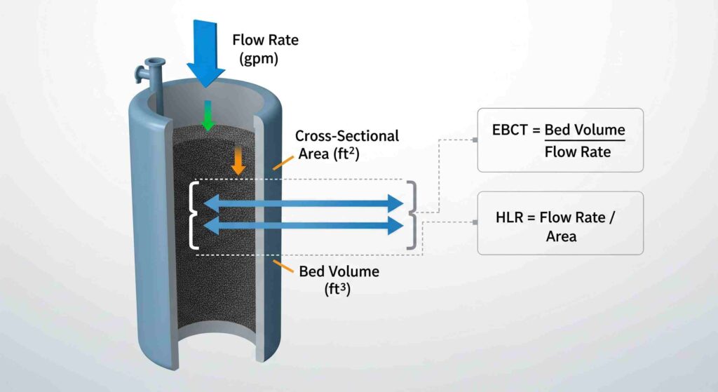
Empty Bed Contact Time (EBCT): The Key to Adsorption Efficiency
EBCT is the most critical design parameter in a GAC system. It represents the theoretical time that the fluid is in contact with the carbon media, assuming the vessel were empty. A longer EBCT allows more time for the adsorption process, resulting in higher removal efficiency.
Formula: EBCT (min) = Bed Volume (gallons) / Flow Rate (gpm)
Typical Values: The required EBCT varies significantly depending on the target contaminant.
| Contaminant Type | Typical EBCT (minutes) |
|---|---|
| Chlorine Removal | 2 – 5 |
| Taste & Odor Removal | 5 – 10 |
| Volatile Organic Compounds (VOCs) | 10 – 20 |
Superficial Velocity & Hydraulic Loading Rate (HLR): Managing Flow Dynamics
Superficial velocity, often expressed as Hydraulic Loading Rate (HLR) in liquid phase applications, is the velocity of the fluid as it passes through the empty cross-section of the vessel. It is a key factor in managing pressure drop and ensuring an even flow distribution through the carbon bed.
Formula: HLR (gpm/ft²) = Flow Rate (gpm) / Cross-Sectional Area (ft²)
Recommended Ranges: For typical taste, odor, and chlorine removal, service flow rates of 5 gpm/ft² are practical. Lower HLRs (2-4 gpm/ft²) are often used for more difficult-to-adsorb contaminants to increase contact time and prevent channeling.
Bed Depth and Aspect Ratio: Optimizing Mass Transfer
The physical dimensions of the carbon bed are crucial for performance. A sufficient bed depth ensures that the mass transfer zone—the area where adsorption is actively occurring—is fully contained within the media.
- Minimum Bed Depth: A minimum depth of 26-30 inches is recommended for most applications to prevent short-circuiting, where water bypasses the carbon media.
- Relationship: Bed depth, EBCT, and HLR are interconnected. For a given flow rate, increasing the bed depth will increase the EBCT, while increasing the vessel diameter (and thus the cross-sectional area) will decrease the HLR.
Section 3: System Configuration—Choosing the Right Operational Setup
GAC systems can be configured in several ways, each with distinct advantages for different operational goals.
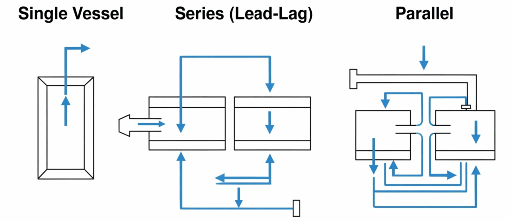
Single Vessel (Downflow): The Simplest Configuration
This is the most common and straightforward setup, where water flows downward through a single vessel containing the GAC bed. It is simple to operate and cost-effective for applications where complete contaminant removal is not critical or where the carbon usage rate is low. Its primary disadvantage is the Risk of premature breakthrough as the carbon becomes exhausted.
Series Configuration (Lead-Lag): Maximizing Carbon Utilization and Preventing Breakthrough
In a series or “lead-lag” configuration, two or more vessels are piped one after the other. The first vessel (the “lead”) does most of the adsorption work. The second vessel (the “lag”) acts as a polisher, capturing contaminants that break through the lead vessel. When the lead vessel is fully exhausted, it is taken offline for media replacement. The lag vessel is then moved into the lead position, and a fresh vessel is placed in the lag position. This configuration maximizes the use of the carbon and provides a robust safeguard against effluent non-compliance.
Parallel Configuration: Handling High Flow Rates
A parallel configuration is used for processes with very high flow rates that would require an impractically large single vessel. The total flow is split between two or more vessels operating side-by-side. This allows for using smaller, more manageable vessels while maintaining the required HLR and EBCT for the overall system.
| Configuration | Pros | Cons | Best For |
|---|---|---|---|
| Single Vessel | Simple, lowest capital cost | Risk of premature breakthrough, inefficient carbon use | Non-critical applications, low contaminant loads |
| Series (Lead-Lag) | Maximizes carbon life, prevents breakthrough | Higher capital cost, more complex piping | Critical applications, high-value streams, regulatory compliance |
| Parallel | Handles very high flow rates, operational flexibility | Higher capital cost, requires flow balancing | Municipal treatment, large industrial processes |
Section 4: Operational Design—Planning for Backwashing and Monitoring
A GAC system design is incomplete without provisions for long-term operation and maintenance. Backwashing and monitoring are essential for ensuring sustained performance.
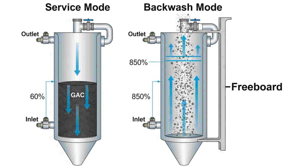
Designing for Effective Backwashing
Over time, the GAC bed will trap suspended solids and can become compacted. Periodic backwashing is required to clean and regrade the bed.
- Purpose: To remove trapped particulates, eliminate flow channels, and lift and resettle the carbon bed to prevent compaction.
- Required Backwash Flow Rate: A flow rate of 10-12 gpm/ft² is typically required to fluidize the bed.
- Target Bed Expansion: Backwashing aims to achieve a 30-40% expansion of the bed depth, which allows trapped particles to be flushed out.
- Freeboard Requirements: The vessel must have adequate freeboard (space above the media) to accommodate this expansion without losing carbon out of the top of the vessel. The standard design requirement is at least 50% of the bed depth.
Establishing a Monitoring Plan
A robust monitoring plan is the only way to track performance and determine when the carbon media needs to be replaced.
- Sample Port Locations: Install sample ports at the system influent, the system effluent, and, for series configurations, between the lead and lag vessels.
- Key Monitoring Parameters: Regularly monitor the pressure drop across each vessel to detect fouling. Most importantly, periodic analytical testing of the effluent for the target contaminants is conducted to track performance and anticipate breakthroughs.
Section 5: A Practical Design Example: Step-by-Step Walkthrough
To synthesize these concepts, consider the following design scenario:
- Objective: Design a GAC system to remove chlorine from a water stream.
- Flow Rate: 100 gpm
- Target Contaminant: Free Chlorine
- Determine Design Parameters
From our table, a typical EBCT for chlorine removal is 3 minutes.
A standard HLR for chlorine removal is 5 gpm/ft². - Calculate Required Bed Volume
Rearranging the EBCT formula:Bed Volume (ft³) = [EBCT (min) * Flow Rate (gpm)] / 7.48 (gal/ft³)
Bed Volume = [3 min * 100 gpm] / 7.48 = 40.1 ft³ - Calculate Required Vessel Area
Rearranging the HLR formula:Area (ft²) = Flow Rate (gpm) / HLR (gpm/ft²)
Area = 100 gpm / 5 gpm/ft² = 20 ft² - Determine Vessel Diameter
Area = π * (Diameter/2)² => Diameter = √[(4 * Area) / π]
Diameter = √[(4 * 20 ft²) / 3.14159] = 5.05 ft. We would select the next standard vessel size, likely a 5.5-foot diameter vessel. - Calculate Bed Depth
Bed Depth (ft) = Bed Volume (ft³) / Area (ft²)
Bed Depth = 40.1 ft³ / 20 ft² = 2.0 ft (or 24 inches). This is slightly below the recommended minimum of 26 inches. We would increase the bed volume to achieve a 2.5 ft (30 inch) depth, providing a longer EBCT and a greater safety margin.
Your Blueprint for a High-Performance GAC System
Effective GAC adsorption system design is a systematic process that balances hydraulic performance, adsorption kinetics, and operational reliability. By starting with a thorough pre-design assessment and applying the core engineering calculations for EBCT, HLR, and backwashing, engineers can move beyond simple carbon selection to create a truly optimized purification system. This methodical approach ensures that the final installation will be efficient, robust, and capable of consistently meeting its treatment objectives.
Design Principles Checklist: A Final Review
- Have all influent parameters been identified and quantified?
- Is the EBCT sufficient for the most difficult-to-adsorb target contaminant?
- Is the HLR within the recommended range to ensure good flow distribution?
- Does the bed depth meet the minimum requirement to prevent short-circuiting?
- Is there sufficient freeboard (min. 50%) for proper bed expansion during backwash?
- Does the system configuration (single, series, parallel) match the operational goals?
- Are sample ports installed to allow for adequate performance monitoring?